GGU-FOOTING: Represent results in the footing plan view (Example 3)
Select the "Output preferences/Footing plan" menu item or click in the "Plan view" drawing element at the right side of the diagram. (Note: The footing analysis diagram is here when analysing in "Multiple footings" mode).
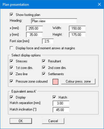
Activate the "Pressure zone coloured" check box. Press the "Colour press. zone" button and select a quiet red from the box (or perhaps not). Confirm with "OK".
In the plan view at the right the pressure zone is now coloured.
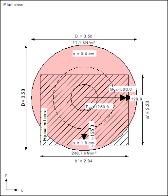
The graphic also contains:
- the characteristic forces Mx,k, My,k, Hx,k and the vertical force Fv,k (= resultant, marked by a cross).
- the 1st core dimension.
If the resultant is within this rhombic area, the complete footing is under pressure. - the 2nd core dimension.
If the resultant is within this elliptical area, a base tilt will occur. - the equivalent area A'.
This region is additionally labelled at the edge with a' and b'. - the four corner stresses or, in our case (with base tilt), the stresses at the five corners of the pressure zone.
- the settlements at the four characteristic points.
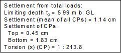
The resulting torsion can be read from the pad footing legend at the lower left of the screen.